January 2009
Axis of Rotation Metrology
In the history of machine tools, spindles have been very good relative to other bearings and structures on the machine. So Quality professionals have developed a cache of tools – like ball bars, grid encoders and displacement lasers – to help them characterize and understand the geometry of the structural loop. But as machine tools have improved in their capability and precision, and the demands of part-geometry and surface finish have
become more critical, errors in spindles have become a larger percentage of the total error.
Once you have done all you can to improve the stiffness, damping, geometry and thermal stability of your machine, and the machine operator is using the best machining practices, the next frontier is to study the errors in the spindles. The ultimate roundness and surface finish that may be achieved by a precision metalcutting machine tool is determined by the performance of its spindles. By characterizing and routinely checking
spindles, part quality can be predicted and controlled.
The focus of this article is to summarize the groundwork already established for using spindle metrology to deterministically improve manufacturing processes. As a bonus, and something the pioneers of spindle metrology would all be quick to point out, is that spindle testing, which is defined in the standards now as “tool to work,” is also an excellent new diagnostic tool for other error sources in the machine.
The Standards which most specifically refer to the quality of precision spindles are: ISO-230-7, “Geometric accuracy of axes of rotation” and ASME B89.3.4-1985, “Axes of Rotation, Methods for Specifying and Testing.” These standards are based on the concept of an “axis
of rotation,” which is a line segment about which rotation occurs. Spindle “run out” is an often used term, but it is not consistent with standards for describing spindle precision. Surfaces have run out; axes have error motions.
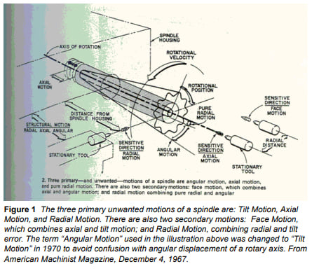
There are three basic spatial error motions in spindles: Radial, axial and tilt (Figure 1). We will see later that spindle error motions are also characterized by frequency and by sensitive direction.
How the testing is done
Over the last 50 years, Axis of Rotation Metrology has developed into a standard for characterizing spindles and understanding the capabilities of a machine. The measurement technique involves high bandwidth, noncontact capacitive sensors with nanometer-level resolution. The sensors reference precision pins or spheres that are mounted to the rotating spindle as targets. So with a three probe system, (two probes arranged radially at 90° from
each other, and one axially centered on the axis for X, Y and Z), a point may be referenced in 3-D space. A five probe system (Figure 2) with two spherical targets may reference two points, and so tilt errors of the spindle may also be known.
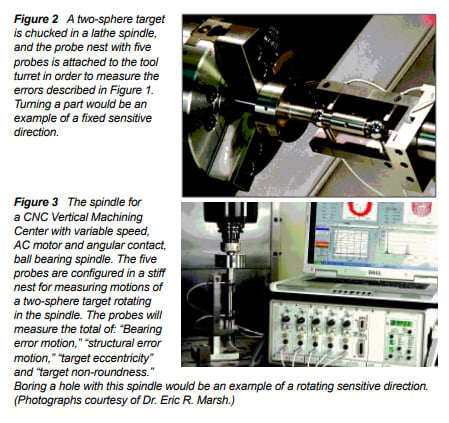
The signals from these five probes each represent a fire hose of information about the spindle’s performance, recording spatial errors and clocking them by frequency. Data can be taken at over 100,000 rpm. The signals may be viewed on an oscilloscope, run though Fast Fourier Transform (FFT) and/or software used to conceptualize the results. (See Figure 3.) Because the spherical artifact is difficult to perfectly align with the axis of rotation, it will have an eccentricity. This eccentricity may be used as a tachometer to phase the data streams with the rotation of the spindle (when an encoder is not conveniently available) and represents an error that is easily subtracted out (like a roundness measuring machine would). This technique allows for phasing a linear data stream (as shown in Figure 7) into polar plots (as seen in Figures 4, 5 and 6.)
What we find in the data, after subtraction of eccentricity, is that some errors are Asynchronous; that is different every time around. If we average the Asynchronous data we have what is called Average Error (per the ASME B89.3.4-1985) now called Synchronous error by the ISO 230-7, and defined as the portion of the total error motion that occurs at integer multiples of the rotational frequency (See Figures 4, 5 and 6.) We will see that asynchronous errors are a main determinant of work-piece surface finish, and synchronous errors are the main determinant of work-piece geometry.
Synchronous (average) error motions
After subtracting out the eccentricity mentioned above, and averaging asynchronous motions, we have what’s called “Synchronous Error Motion.” In
most cases this would be considered the spindle error motion. In cases of very high precision spindles, where the 25 or 50 nanometer errors
in the target become a significant percentage of the total error motion, another measurement procedure called “Donaldson Reversal” may be
employed to subtract out the errors that are in the target.
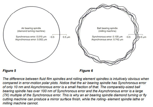
Synchronous (average) errors are clearly illustrated in plots of air and hydrostatic spindles as the error repeats, every time around. (See Figure 5.) This is, in large part, due to the fact that there is just one rotating element. Error motions in air bearing spindles are often less than 25 nanometers (or
one-millionth-of-an-inch). In such a case, Donaldson Reversal would be a necessary methodology as the error motion of the spindle is likely less than the non-roundness of the target.
For a lathe, unbalance, which results in vibrations that you may think would affect surface finish, actually does not Unbalance causes a once per revolution disturbance that is repeatable. It is a synchronous error. If you have a part in a lathe spindle that is not balanced and you bore a
hole in it, it may have good surface finish and roundness but when you slow the spindle down the whole will be eccentric.
With capacitance probes it is possible to measure the eccentricity (run out) of the turned surface at different speeds. With perfect balance, the radial load on the spindle does not change with speed and so there would be no run out at any speed. In a different situation, the unbalance of a grinding wheel spindle will have a surface finish effect determined by the relative speed of the spindle and work piece.
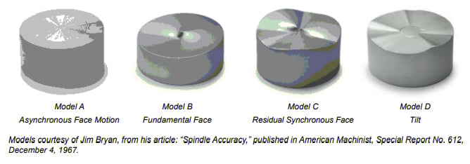
Fundamental synchronous and asynchronous axial motion is measured on the axis of rotation. It is very important when flatness or form at the center of the part is important. This would be the case in manufacturing optics. The face motions are measured some noted distance from the center, and would be the same as the axial motion in the absence of tilt motion. Because they are both measured on the face, both are axial motions and so they cause flatness errors when facing parts.
However, fundamental axial face motions will create a part that has the property of circular flatness, that is, the overall surface is not flat, but provides a “flat sealing surface” at any given radius. If you were to put the part on a roundness checker, and measure flatness at some radial distance from the center, you could adjust the part into reading flat at that radius, but the flat surface will not be perfectly square to the axis it was turned on, or the
reference surface the part was chucked on. This may be acceptable for a sealing surface, but it would not be a good thing for a bearing surface.
The utility of measuring error motions in spindles became evident as hydraulic systems were being applied to military aircraft. Leaky hydraulic fittings were a maintenance headache and a hazard. A study by the military to improve the effectiveness of taper seals revealed that residual face motions of spindles making tapered seals would compromise the geometry of the tapers produced and its ability to seal.
Residual synchronous face motions are motions left over after the fundamental (the once around) errors are subtracted; they are still synchronous but are at other integer multiples of the rotation frequency. Residual face motions result in parts that are not flat at all, not even circularly flat. Controlling the property of residual face motion is critical whether you are making seals or bearing races and, because tilt is involved, this is especially true with large diameters.
Asynchronous error motions
Asynchronous error motions are a predictor of surface finish, and are best illustrated in error motion plots of rolling-element bearings. Because rolling-element bearings have “constituent elements” (rollers, inner race and cages) that are not perfect and have different rotational frequencies, error motions of the spindle appear random. They are not actually random, the determinist view point is that they can be predicted. In rolling-element spindles, these asynchronous motions are generally much larger displacements than the synchronous motions. (See Figures 4, 5 and 6). Over many revolutions, the polar plot develops into a fuzzy band and the thickness of this band represents the asynchronous error motion of the spindle.
This is likely to be 100 nanometers in the very best rolling element spindles; 1000 nanometers (1 micron) in good spindles; and 10 microns or more in 500mm or larger diameter bearings.
 The linear plot (See Figure 7) shows how the different elements, with their different rotational frequencies, produce what appears to be non-repeatable motion in the summation of their signals (top). The portion of the signal that is asynchronous is the determinant of surface-finish capability. The error motions do repeat though after many revolutions, and can be predicted to some degree. An analogy can be made with the sun, which rises differently each day but is, after many rotations, repeatable.
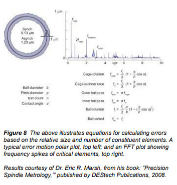
Figure 7 also shows that the error-motion signal may be decomposed into frequency components, and that doing so can result in a better understanding of the factors causing observed motion. For rolling element bearings, characteristic frequency equations can predict error motion
encountered during rotation that are a function of the geometry of the bearing (diameter of races, number of rolling elements, diameter of rolling elements, etc.).
The Fast Fourier Transform (FFT) is the most common method for separating the frequency components of a signal. An example of this can be seen in Figure 8 for a single row, deep-groove bearing. Note that the cage, ball pass and outer race frequency spikes are identified in the chart.
Rolling element bearings can have nanometer (one thousandth of a micron) repeatability when turning though angles of less than 360 degrees and then returning to the starting position. This is because, in less than one revolution, the constituent elements do not precess. That is, all of the components come back to their original locations with respect to each other.
If the error motions of the spindle are plotted for 10 revolutions and then reversed, the error motions will retrace exactly, showing that the motion of the roller bearing spindle is deterministic. So the Gaussian distribution shown in Figure 8 across the asynchronous error band indicating random motion is not correct, but is of utility, illustrating at a glance the distribution of the errors in the band.
Summary
So, what is important if you are selling bearings for spindles? First, talk about Low Error Motions – not “Non Repeatable-Run Out” (NRR or Run Out) – to show you are familiar with Axis of Rotation Metrology. Remember, error analysis data encompasses all spindle errors, including structural errors both thermal and from external vibrations. Don’t let your bearings get blamed for structural vibration from someone’s coolant pump. Structural Error Motion can be measured quickly and simply by indicating from the tool to the spindle headstock. This is called stationary-point run out. Spindle drive systems can influence and print though into the error motion plot, too. Error at the frequency of the motor poles is a dead giveaway that this is the case. Thermal drift of the spindle axis as it warms up will be the biggest error, but remember that it affects position, not roundness or surface finish, and is caused by heat, not bearing precision.
If you are manufacturing bearings or spindles, take care that the error motions of your spindles are not limiting the quality of the bearings you manufacture. The synchronous error motions of your work-holding spindles will determine the roundness or flatness of the parts you manufacture.
Residual face error motion of work spindles can cause flatness errors of races for large roller bearings. These errors can also change the intended profile of a spherical race. Surface finish is dependent on the asynchronous error motion of both the work spindle and the grinding
wheel spindle. Dramatic surface finish improvements can be made by characterizing and improving spindles using Axis of Rotation Metrology.
About the Author
The author, Drew Devitt, is the Founder and Chief Technology Officer for New Way Air Bearings, Aston, PA, USA. He is past president of the American Society for Precision Engineering, and wrote this as a member the Bearings Specialist Association, Education Committee.
ddevitt@newwayairbearings.com
Bibliography
Bryan, Jim. “Spindle Accuracy,” American Machinist, Special Report No. 612, Pages 149-164, December 4, 1967.
Bryan, Jim. “Tutorial On Axis of Rotation,” Annual Meeting of the ASPE, November 1, 1999.
Holzhauer, Wolfgang. “Tutorial On Axis of Rotation,” Annual Meeting of the ASPE, November 1, 1999.
Marsh, Eric R. Precision Spindle Metrology, DEStech Publications, 2008.
Moore, Wayne R. “Foundations of Mechanical Accuracy,” The Moore Special Tool Company, 1970.
Donaldson, R. R. “A Simple Method for Separating Spindle Error from Test Ball Roundness Error,” CIRP annals volume 21/, 1972.
References
The author would especially like to thank Jim Bryan and Eric Marsh for their effort and input in this work.
Jim Bryan
Precision Engineering Consultant (and the Father of Axis of Rotation Metrology)
Bryan Associates
5196 Golden Road, Suite 3
Pleasanton, CA 94566 USA
925.846.1253
925.989.9252
925.484.5342
jimb123@aol.com
Dr. Eric R. Marsh
Professor of Mechanical Engineering Machine Dynamics Research Laboratory
Penn State University
137 Reber Building
University Park, PA 16802 USA
814.865.5242 office
emarsh@psu.edu
Wolfgang Holzhauer Ph.D
Timken Company
Research Specialist the Timken Company
RES-09, 1835 Dueber Avenue, SW
P.O. Box 6930, Canton, OH 44706-0930 USA
330.471.2265
Lion Precision
651.484.6544
info@lionprecision.com
www.spindleanalysis.com
www.lionprecision.com
Mel Liebers
Professional Instruments
4601 Highway 7
Minneapolis, MN 55416 USA
612.927.4496
www.airbearings.com
Drew Devitt
New Way Air Bearings
50 McDonald Blvd.
Aston, PA 19348 USA/
610.494.6700
ddevitt@newwayairbearings.com
www.newwayairbearings.com
